Siirry takaisin
LISÄTIEDOT
| TUOTTEEN LISÄTIEDOT | |||||||||
|
|||||||||
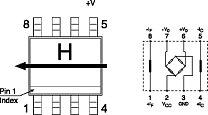
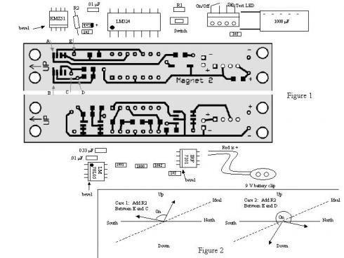
| Tuotteen kuvaus: 1 KMZ51 1 IRF7101 1 LM324 1 LM78l05 1 switch 1 terminal block 2 0.01 uF capacitor green line on cardboard 1 0.33 uF capacitor red line on cardboard 1 1.0 uF capacitor CAb 1 1000 uF capacitor 3 1000 ohm resistor 102 2 10 kohm resistor 1002 1 100 ohm resistor 1000 1 1.0 ohm resistor 1R0 1 2.2 ohm resistor 2R2 1 4.3 Mohm resistor yellow-orange-green-gold 1 3.0 Mohm resistor orange-black-green-gold 1 2.0 Mohm resistor red-black-green-gold 1 1.5 Mohm resistor brown-green-green-gold 1 1.0 Mohm resistor brown-black-green-gold 1 9V battery clip 1 PC board Magnet 2 Assembly and Calibration 1. Compare the traces on the PC board to Figure 1 to check for undesired shorts between the traces. I've looked at all of the boards already, but it doesn't hurt to double check. 2. Solder all components down, as shown in Figure 1 or 3, except for R1 and R2Start with small resistors, capacitors and switch. Be careful with the unmarked brown components, two are 0.01 uF capacitors (green line on cardboard) and one is a 0.33 uF capacitor (red line) Solder chips next. Make sure the chip is oriented properly. The text, bevel and pin 1 mark should correspond to the figure. One sensor that didn't work was returned to me and had one chip oriented the wrong way. For each chip, tack down one corner lead, check the alignment of the other leads, solder down the opposite corner. Check again and then finish the other leads. End with terminal block, 1000 uF capacitor and battery lead. Double check all of your solder joints. Most magnetic sensor anomalies have been due to poor or missing solder joints. 3. Measure resistance across points A and B. Add resistor R1 so that 3.3 ohm < Rab +R1 < 6 ohm, Try to make it around 5 ohms. 2R2 = 2.2 ohm, 1R0 = 1.0 ohm If Rab falls into the above range by itself, solder a small wire (0 ohm) in place of R1. Rab will *not* change after R1 is added. 4. Attach on/off switch or jumper wire across indicated terminal block positions. Attach test LED across other 2 positions (right-most position is +) 5. Attach 9V battery to clip, turn the on/off switch on and depress small switch to reset sensor 6. Find elevation angles at which LED goes on, testing away from large ferrous objects and magnets. Highest elevation angle should be towards magnetic north and the lowest to magnetic south. Ideally you want the angle above horizontal to the north to be equal to the angle below horizontal to the south, about 20 degrees in the northeast.(see figure 2)If the angle to the north is too big (case 1), add R2 between vias E and C. If the angle to the north is too small or negative (case 2), add R2 between vias E and D. Start with the 4.3 Mohm resistor. Don't solder R2 until you are close to the ideal case. The resistors can be identified as follows: 4.3 Mohm = yellow orange green gold 3.0 Mohm = orange black green gold 2.0 Mohm = red black green gold 1.5 Mohm = brown green green gold 1.0 Mohm = brown black green gold Use of magnetic apogee sensor Mount magnetic apogee sensor in rocket with the KMZ-51 end up. Attach the on/off switch leads as before. For the e-match/flashbulb connection, I run leads to a phono jack such that when the jack is plugged in, the ejection charge is disconnected. I wire an LED into the jack which allows the unit to be tested at the launch pad just prior to launch. Here's my checklist 1. Prep rocket and ejection charge 2. Insert phono jack 3. Assure the RSO that this sensor really does work 4. Turn on power 5. Reset sensor via small switch 6. Test operation by tipping rocket over to see if LED lights at the expected angle 7. Load rocket onto launch rod 8. Remove phono plug 9. Launch and enjoy an apogee ejection Tips/Cautions Don't use steel or other magnetic components near the KMZ51, use nylon, aluminum or brass instead. Mount the sensor on opposite side of rocket from launch lugs. I've never had a problem, but the steel launch rod may alter the local field of the Earth. Avoid running wires with high currents near the sensor as well, as this may trigger the sensor prematurely. If you are nervous about the magnetic fields on the pad, follow the checklist through step 6. Then remove the rocket from the pad and repeat step 5. If the sensor still works as expected, finish the checklist. If not, you may have a magnetized launch rod. Try a different rod or pad. The sensor has been tested successfully with AG-1 and AG-1B flashbulbs and Daveyfire N28-B and N28-F electric matches. The sensor draws about 6 mA and should run for ~100 hours on a 9V Duracell. If you want to mount this in a BT-5 some modifications are required. Sand down the edges of the PC board just to where the traces begin. Don't solder on the terminal block, but rather run wires directly to the PC board. You'll need a different battery, so don't use the supplied battery clip. I bought a few custom 9V lithium batteries that are about 11 mm or so in diameter that fit. You can also use a small 12 V battery (Duracell MN21 type) which will fit in a Radio Shack N-cell battery holder. |
|||||||||
 |
|||||||||
 |
|||||||||
 |
|||||||||
